Here are some basic design guidelines to follow to increase the feasibility of producing your part using Powder Metallurgy. The engineers at Perry Tool & Research will work with your design teems to ensure that a part meets your exact requirements, is well engineered, and is economical to produce.
| Dimensions The maximum size and dimension of a part are determined by the press capacity. Contact us to discuss your specific part requirements. |
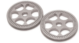
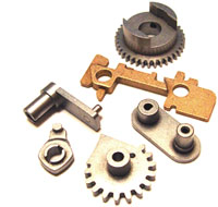 Shapes Shapes The P/M process is not shape-sensitive. Parts can be uniquely shaped or designed to combine two single parts into a complex, one-piece PM part. The part combinations are only limited to the design concept. |
| Tolerances The P/M process is cost effective in producing close-tolerance, parts to final dimensions with excellent part-to-part reproducibility. Contact us to discuss your specific part requirements. |
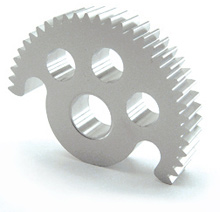
 Holes Holes Holes can be round, D- or double D-shaped, blind, tapered, and can include keyways or splines. Lightening holes are often added to parts to reduce weight and material costs. |
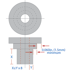 Wall Thickness Wall Thickness As a general rule, walls should not be thinner than 0.060 inch (1.52 mm) and the ratio of the length to wall should be less than 8:1 for tool strength and to ensure that the powder properly fills all sections of the die for proper part density. |
| Flatness The flatness of a part depends on the part thickness and surface area. Perry Tool & Research has the ability to hold the flatness of a part to very tight tolerances. We will work with your design team to achieve your specific design requirements. |
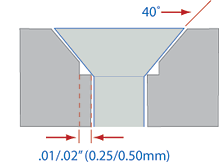
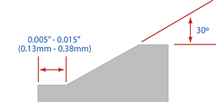 Edges Edges The edges of a part should be designed with chamfers rather than radii to prevent burring. A 30-45 Deg. chamfer with a 0.005-inch (0.13mm) to 0.015 inch 0.38mm) flat will eliminate feathered edges, which are undesirable. |
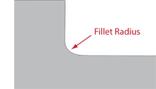 Fillets and Radii Fillets and Radii Parts designed with generous fillet or radii are more economical, longer lasting, more easily produced and have greater structural integrity. |
 Countersinks CountersinksCountersinks, which can be designed in a part for a screw or bolt head, should be 0.010 inch (0.25 mm) nominal flat. |
 Bosses Bosses Bosses are often added to a part to eliminate the need for washers. Boss forming cavities in the tools should be 15% or less than the part height. The draft angle should be at least 12 Deg. per side to avoid sticking. |
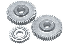
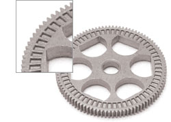
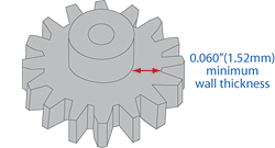 Hubs Hubs Hubs are complementary part sections to gears, sprockets, or cams. Allow for a 0.060” (1.52mm) minimum wall thickness between the hub O.D. and the root diameter of the gear or sprocket. |
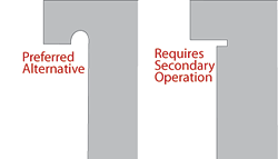 Undercuts Undercuts A curved undercut can be formed during PM compaction. This type of undercut can be designed as an alternative to an undercut that is perpendicular to the pressing direction, which can only be made with a secondary machining operation. |
 Slots and Grooves Slots and Grooves Curved, semicircular, or rectangular grooves can be pressed into the end of a part by projections on the punch face. Our engineers can assist your design team determine the feasibility of your specific groove requirement. |
 Surface Finish Surface FinishWith some manufacturing processes, producing the desired surface finish on a part can require an additional finishing process. Excellent surface finish is an inherent feature of P/M components. They compare favorably with ground or ground-and-polished surfaces of wrought and cast components. The overall smoothness and surface reflectivity depend on density and the tool finish. Perry Tool & Research can produce part surface finishes down to 4 micro inches (0.10 micrometers). |
Our design and engineering staff can assist you on design solutions, material selection and tolerance considerations or answer any questions you may have. Call us at 510-782-9226 or email us.